What ESP-KVM needs from a board
- ✓ 32 MB of PSRAM. It has the 32 MB of PSRAM the video needs.
- ✓ A camera connector the capture board fits. The HDMI capture board's Raspberry Pi camera ribbon fits its camera connector. Connector: on the carrier board (its CSI1 / CAM1 connector).
- ✓ High-speed USB towards the target. Its high-speed USB comes out where it can face the target as a device.
- ✓ A network. It has a network: Ethernet, or Wi-Fi through a co-processor.
Read from the maker’s documents, checked 2026-11, not from a board in hand.
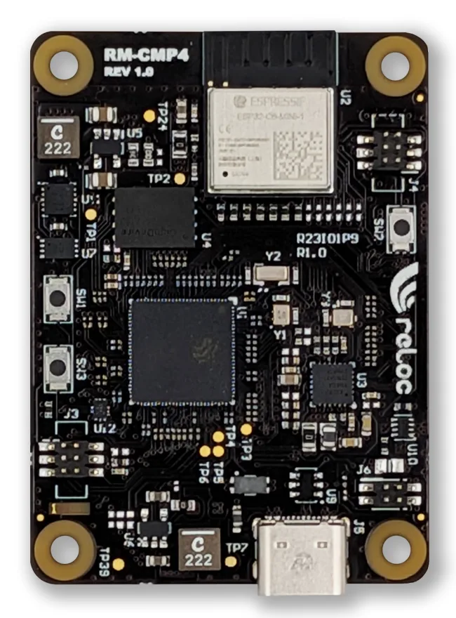
The SCINTIX P4 is a module with the same connectors and pin assignment as the Raspberry Pi CM4 and CM5. It has the ESP32-P4NRW32X (rev 3.x) with 32 MB of PSRAM, an Ethernet PHY on the module and an ESP32-C6 on SDIO. The camera socket and the USB ports come from whatever carrier board it sits on.
RELOC's carrier guide answers most of what ESP-KVM needs. The module has one camera interface, CSI1, with 2 lanes, so the carrier's CAM1 connector is the one to use. CAM0 is not supported. On the Waveshare CM4 to Pi 4B adapter the camera was tested by RELOC, and its USB-C port works as a device port on the high-speed controller. That is the setup a port would start from. On the CM4 IO Board the main USB port goes to a hub, so it is a host port there.
A port would need a board definition for the module: the CSI pins, the PHY pins, the SDIO pins to the C6 and the USB routing (the J6 jumper on the module changes it). The carrier also matters: the capture board's ribbon has to fit its CAM1 socket, and its GPIO voltage has to be set to 3.3 V. I have not found a published schematic for the module.
Have one?
One request is enough: I add a board as soon as someone who has it can try a test build.
- Open a board request in Discussions. The form asks for the board's shop page, its schematic if there is a link, the chip marking and the capture board you have.
- I make a test image from the schematic and post it in the thread.
- You flash it on the flasher with Install another version from a file, and tell me what works. The flasher's Back up the flash keeps the board's old firmware.
- Once the picture, the keyboard and the network work, the board goes into the catalog with its own image and updates.