What ESP-KVM needs from a board
- ✓ 32 MB of PSRAM. It has the 32 MB of PSRAM the video needs.
- ✓ A camera connector the capture board fits. The HDMI capture board's Raspberry Pi camera ribbon fits its camera connector. Connector: 15-pin, Pi order.
- ✓ High-speed USB towards the target. Its high-speed USB comes out where it can face the target as a device.
- ✓ A network. It has a network: Ethernet, or Wi-Fi through a co-processor.
Read from the maker’s documents, checked 2026-11, not from a board in hand.
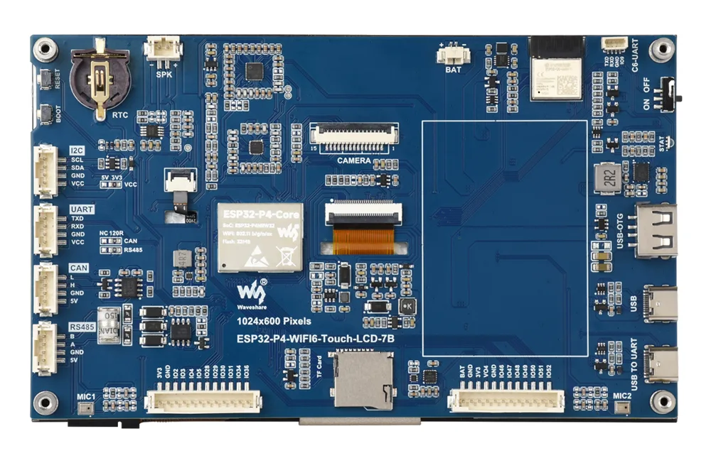
A 7" 1024x600 touch display board in Waveshare's ESP32-P4-WIFI6-Touch-LCD line. It carries Waveshare's ESP32-P4-Core module (an ESP32-P4NRW32X, so rev 3.x, with 32 MB of flash), an ESP32-C6-MINI-1 on SDIO and a microSD slot. The 7B-C is the same board sold with an OV5647 camera.
On paper it has everything ESP-KVM needs. The camera connector is a 15-pin 1.0 mm one, and in the schematic its pins follow the Raspberry Pi order: ground, data lane 0, data lane 1, clock, two GPIOs, I2C and 3.3 V. So the capture board's ribbon should plug straight in. The P4's high-speed USB goes to a USB-A socket marked USB-OTG. That socket gets 5 V through a load switch, so until the switch is checked, the lead to the target should be an A-to-A cable with the 5 V wire cut, as on the NANO.
There is no Ethernet, so the network is Wi-Fi through the C6 only. A port needs the board's pins: the C6's SDIO and reset lines, the camera I2C (shared with the touch panel and the audio codec on GPIO7 and GPIO8) and the microSD pins. They are all in the published schematic.
The other boards in the line differ. The 4.3" and 5" ones have a 15-pin 0.5 mm camera connector, which needs a 0.5 mm to 1.0 mm ribbon. The 3.5" one has a 15-pin 0.5 mm connector too. The 4B (a 4" 720x720 screen) has a 15-pin 1.0 mm camera connector, the high-speed USB on USB-C and an IP101 Ethernet PHY whose lines go only to a header, but it uses a rev 1.x ESP32-P4NRW32.
Have one?
One request is enough: I add a board as soon as someone who has it can try a test build.
- Open a board request in Discussions. The form asks for the board's shop page, its schematic if there is a link, the chip marking and the capture board you have.
- I make a test image from the schematic and post it in the thread.
- You flash it on the flasher with Install another version from a file, and tell me what works. The flasher's Back up the flash keeps the board's old firmware.
- Once the picture, the keyboard and the network work, the board goes into the catalog with its own image and updates.