What ESP-KVM needs from a board
- ✓ 32 MB of PSRAM. It has the 32 MB of PSRAM the video needs.
- ✓ A camera connector the capture board fits. The HDMI capture board's Raspberry Pi camera ribbon fits its camera connector. Connector: 15-pin, Pi order.
- ✓ High-speed USB towards the target. Its high-speed USB comes out where it can face the target as a device.
- ✓ A network. It has a network: Ethernet, or Wi-Fi through a co-processor.
Read from the maker’s documents, checked 2026-11, not from a board in hand.
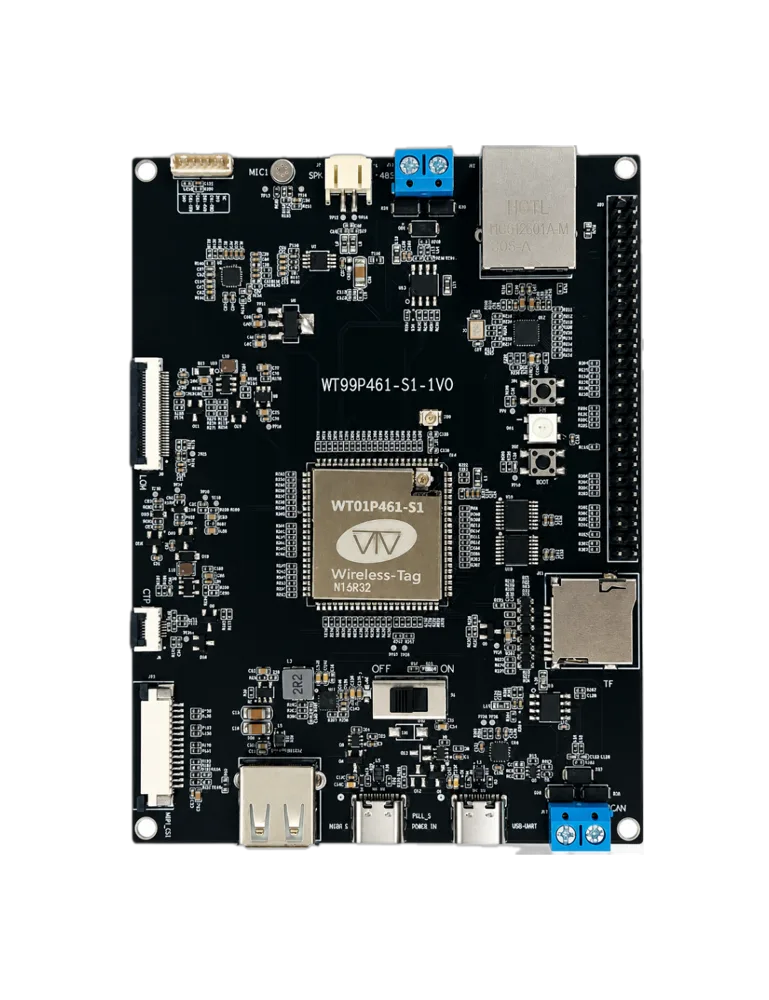
The WT99P461-S1 is a large development board built on the WT01P461-S1 module, an ESP32-P4 rev 3.2 with 32 MB of PSRAM and an ESP32-C61. It has 100M Ethernet through an IP101, RS-485, CAN, audio and a microSD slot.
The camera connector J15 is a 15-pin 1.0 mm one, and the schematic shows the Raspberry Pi order: lanes and clock on pins 2 to 9, CAM_IO0 and CAM_IO1 on 11 and 12, I2C on 13 and 14, 3.3 V on 15. Ethernet gives the network, so the C61 is not needed. It talks SPI, which ESP-KVM does not support yet.
The high-speed USB goes to the USB-A socket J4. A load switch always drives 5 V onto its VBUS, as on the Waveshare NANO. So the lead to the target would be an A-to-A cable with the 5 V wire cut. The USB-C socket J3 is only full speed, and J1 is a USB-UART bridge for flashing. The microSD slot sits on SDMMC slot 1 behind an analog switch on GPIO 33. A port would need the Ethernet PHY pins, the camera I2C pins and that switch.
Have one?
One request is enough: I add a board as soon as someone who has it can try a test build.
- Open a board request in Discussions. The form asks for the board's shop page, its schematic if there is a link, the chip marking and the capture board you have.
- I make a test image from the schematic and post it in the thread.
- You flash it on the flasher with Install another version from a file, and tell me what works. The flasher's Back up the flash keeps the board's old firmware.
- Once the picture, the keyboard and the network work, the board goes into the catalog with its own image and updates.