What ESP-KVM needs from a board
- ✓ 32 MB of PSRAM. It has the 32 MB of PSRAM the video needs.
- ✓ A camera connector the capture board fits. The HDMI capture board's Raspberry Pi camera ribbon fits its camera connector. Connector: 22-pin, Pi order.
- ✓ High-speed USB towards the target. Its high-speed USB comes out where it can face the target as a device.
- ✓ A network. It has a network: Ethernet, or Wi-Fi through a co-processor.
Read from the maker’s documents, checked 2026-11, not from a board in hand.
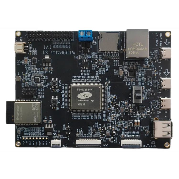
The WT99P4C5-S1 is a large development board built around the WT0132P4-A1 module. It has 100M Ethernet through an IP101GRI, an ESP32-C5 module on SDIO for dual-band Wi-Fi, RS-485, an ES8311 audio codec and a microSD slot.
The camera connector J10 is a 22-pin 0.5 mm one, and the schematic shows the Raspberry Pi 22-pin order: lanes, clock, CAM_IO0 and CAM_IO1 on pins 17 and 18, I2C on 20 and 21, 3.3 V on 22. So a 22-pin Pi camera ribbon from the capture board fits. The high-speed USB goes to a USB-C socket that can work as a device, and also to a USB-A socket. The guide says to use only one of the two at a time. A third USB-C socket is the full-speed port.
The module comes in two versions, N16R32 and N16R32X. Wireless-Tag's own example tells you to check the marking and pick the chip revision to match, so the board can have either a rev 1.x or a rev 3.x P4. The guide gives 360 MHz in one place and 400 MHz in another. ESP-KVM has separate images for the two revisions, so a port needs to know which one is on the board. It would also need the camera I2C and enable pins, the Ethernet PHY pins and the C5's SDIO pins.
Have one?
One request is enough: I add a board as soon as someone who has it can try a test build.
- Open a board request in Discussions. The form asks for the board's shop page, its schematic if there is a link, the chip marking and the capture board you have.
- I make a test image from the schematic and post it in the thread.
- You flash it on the flasher with Install another version from a file, and tell me what works. The flasher's Back up the flash keeps the board's old firmware.
- Once the picture, the keyboard and the network work, the board goes into the catalog with its own image and updates.