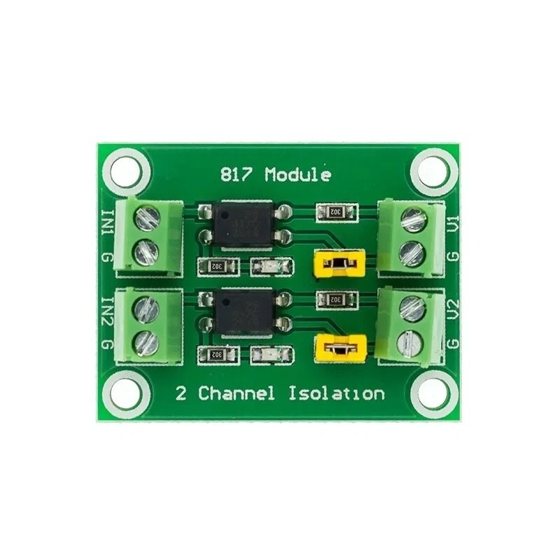
The case's power button is a switch across two pins of the motherboard's front-panel header. An optocoupler closes the same two pins with light, so the machine and the ESP32-P4 board never share a ground. Unlike a relay, it also works the other way: it can read the power LED, so the console shows whether the target is on.
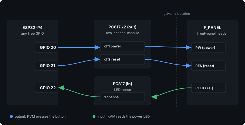
How to wire it
- First board, outputs. IN1 and IN2 to two free GPIOs, the board's GND to the device's GND. The two outputs go across the power switch pins and the reset switch pins.
- Polarity on the switch side. The collector goes to the pin that reads a small positive voltage to ground (measure it on a plugged-in but powered-off machine), the emitter to the other.
- Second board, the LED. PLED+ to its input's +, PLED- to its -, and its output to a free GPIO. The power LED, not the HDD LED: that one only blinks.
- In Settings → Power → ATX wiring, set the power, reset and LED pins. The two buttons come filled in with free pins; the LED is left unset until you wire it. Buttons active-high is on by default; turn it off if your board presses on a low.
Good to know
- The LED side gets only the motherboard's LED current. With the stock input resistor (about 1 kohm) it can read weakly; if the power state jumps around, change that resistor to 220-330 ohm.
- Skip it all and everything else still works: the console just hides the power buttons.
- Not tried on the bench yet; the wiring is from the parts' datasheets.