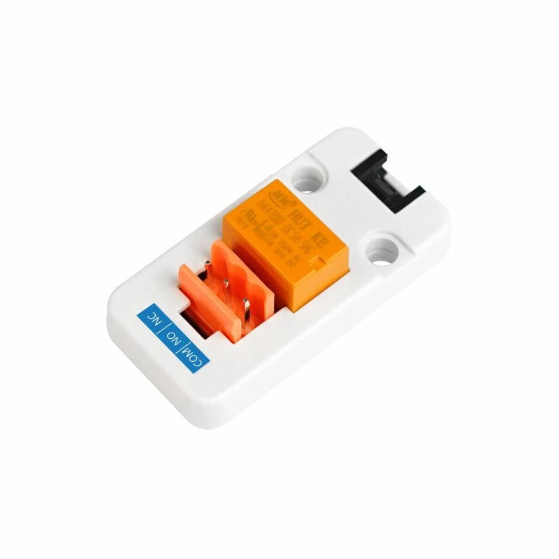
A relay is the same job as the optocoupler board: two contacts that close for a moment, the way the case's own button does. The firmware needs nothing new for it.
How to wire it
- The Grove cable to the board. The yellow wire is the signal.
- COM and NO across the target's power switch pins on the front-panel header. Polarity does not matter to a switch.
- In Settings → Power → ATX wiring, set Power button GPIO to the yellow wire's pin and turn Buttons active-high on: the relay closes when the pin goes high.
One relay is one button. For reset as well, a second unit on another pin, or the two-channel optocoupler board. A relay cannot sense the power LED, so the console cannot show whether the target is on.
On the M5Stack Unit PoE-P4 the Grove port is GPIO 53 (yellow) and 54, the same pair the status display uses there, so it is the relay or the display.
Good to know
- The relay clicks on every press, and it can switch far more than a power button needs.
- Not tried with this unit yet; the wiring is from its documentation.