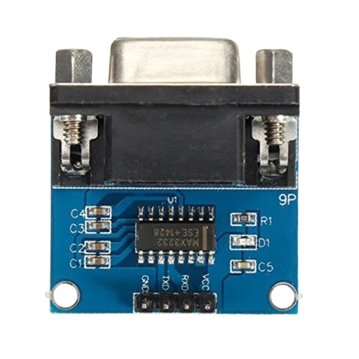
A PC's or a server's COM port is RS-232: about ±12 V, which destroys a 3.3 V pin. This module turns it into 3.3 V logic. Its 4-pin side goes to the ESP32-P4 board, and its 9-pin socket plugs into the target.
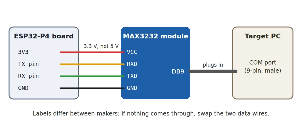
How to wire it
- VCC to 3V3, not 5V. Powered from 5V, its TTL side outputs 5V too.
- GND to GND.
- The device's TX pin to the module's RXD, and the device's RX pin to its TXD.
- The 9-pin socket into the target's COM port. On a server with only an internal 10-pin header, an adapter bracket brings it out.
Then Settings → Power → Serial console: turn it on, pick the two pins and the speed. Any two free GPIOs work; avoid 37 and 38, which many boards wire to their own USB-to-serial chip. On the Function EV board GPIO 5 and GPIO 4 are free. A PC BIOS usually runs at 115200 or 9600, Linux at 115200.
Good to know
- Labels differ between makers. The one in the photo has GND, TXD, RXD, VCC in a row; some print TXD for the pin that receives. If nothing comes through, swap the two data wires; it does no harm at 3.3 V.
- A network switch or a router often has its console on an RJ45 port. That needs a "Cisco" console cable to DB9, then this module.
- A 3.3 V console needs no module. A Raspberry Pi or a router's 4-pin header wires straight to the device's pins.
- I have not run this module myself yet; the wiring is from its datasheet.